Lab 5: Motors and Open Loop Control
In this lab, the motor drivers were installed, which allowed the Artemis board to finally send direct commands to drive the car. Although the motors were mainly driven using open loop control here, the goal is to eventually integrate the sensors into a more robust feedback loop.
Setup:
Before the Artemis board can send commands to the motors, motor drivers (DRV8333) for each motor were installed.
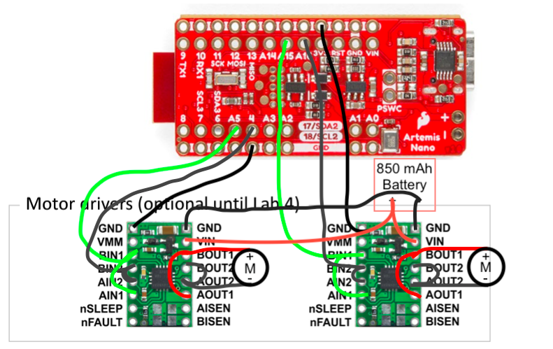
Although we are using motor drivers each with dual outputs, we connect two outputs in parallel to each of the motors to increase the maximum output current and power they can source. As shown in the diagram, this essentially amounts to shorting the outputs A and B for each motor driver:

The Artemis board was then connected to the motor drivers via pins 4, A5, A15, and A16, all of which are hardware PWM pins capable of sending analog signals via analogWrite().
In addition to the motor drivers, a separate 3.7 V 850 mAh battery was used to power the motor drivers and motors.
The main advantages in doing so are a higher power output due to the lack of power regulation from the Artemis board. Furthermore, the higher battery capacity (850 mAh vs 650 mAh) provides a longer battery lifetime, allowing the motors to run for longer in general. Finally, a separate power supply could potentially isolate the Artemis board from possibly power supply noise generated from the power draw of the motor.
Motor Drivers:
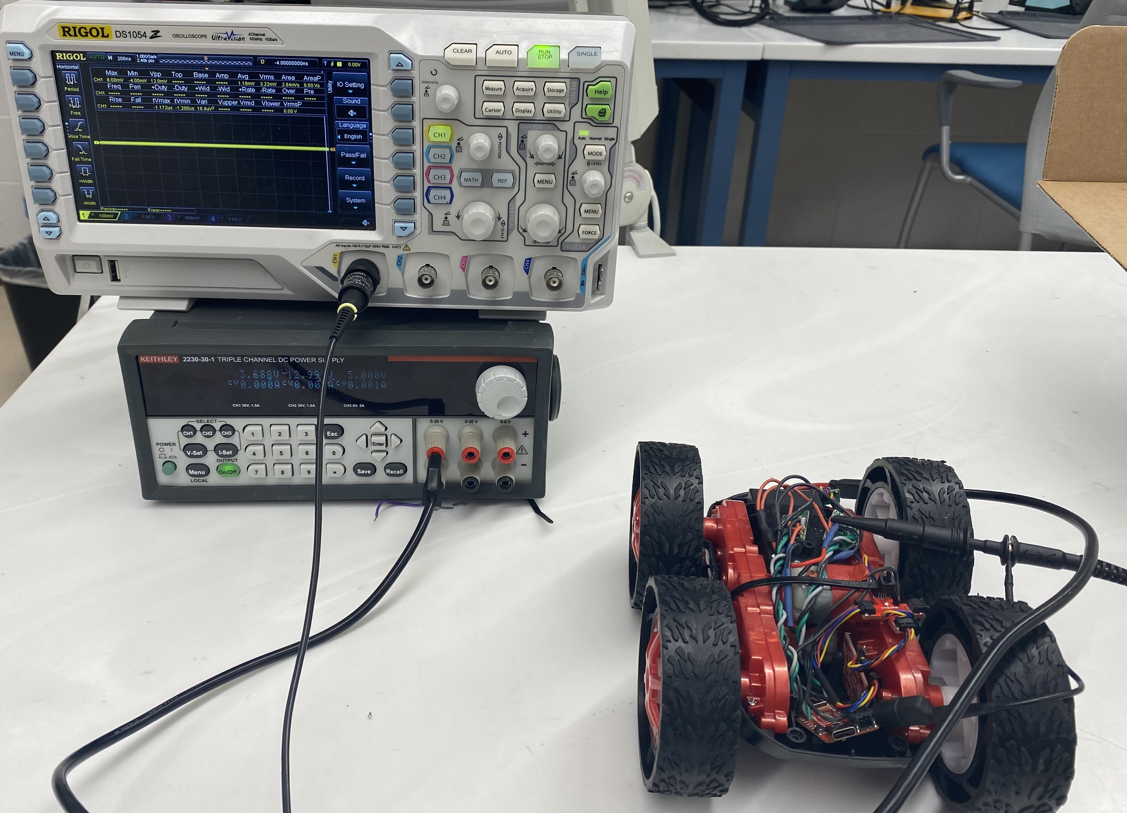
After soldering a motor driver to the Artemis board, the output was first measured via an oscilloscope.
In setting the power supply for the motor driver, a constant voltage of 3.7V was set to simulate the battery voltage. To protect the motor driver, the current was limited to 1.5 A. This may have been a tad too cautious, since according to the datasheet, the paralleled outputs of the motor drivers are capable of sinking up to 3 to 4 A of current.

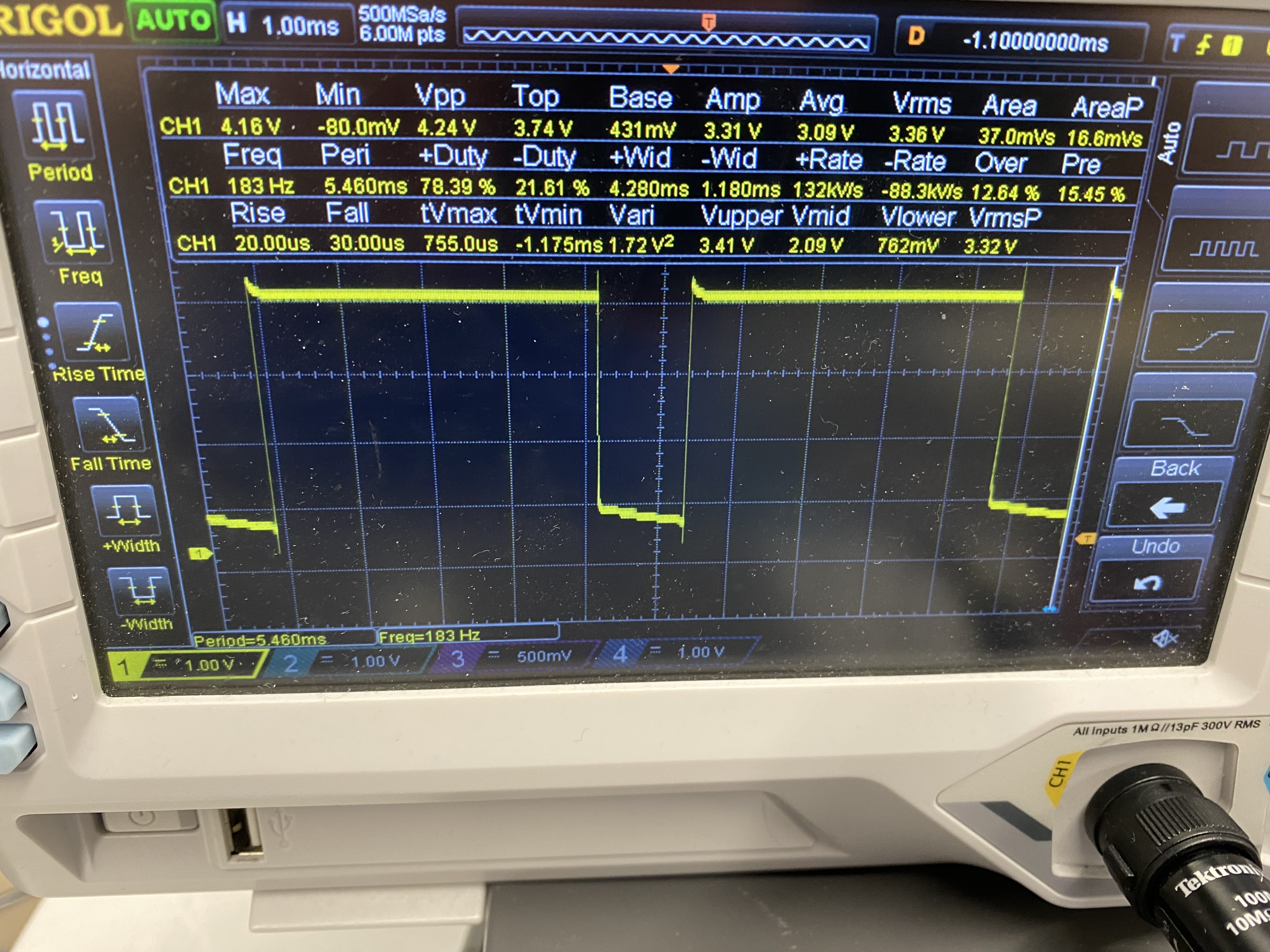
Afterwards, to demonstrate the the motor driver was functional, the following code generated a PWM input:
analogWrite(4,200);
analogWrite(A5,0);
This then generated the following output:

After the correct outputs from the motor driver were confirmed, the motor drivers were then soldered to the motor leads. To test that the motor could drive in both directions, the following PWM commands were used:
// backwards
analogWrite(4,200);
analogWrite(A5,0);
delay(1000);

// stop
analogWrite(4,255);
analogWrite(A5,255);
delay(1000);

// forward
analogWrite(4,0);
analogWrite(A5,200);
delay(1000);

// stop
analogWrite(4,255);
analogWrite(A5,255);
delay(1000);
This generated the following response:
This process was then repeated for the second motor driver, and once both motor drivers were confirmed to work when connected to their respective motors, the 850 mAh battery was soldered to the drivers. After writing a somewhat similar set of PWM commands compared to before (alternating forward, braking, and backward commands) functionality of the entire control circuit was then tested:
Wiring:
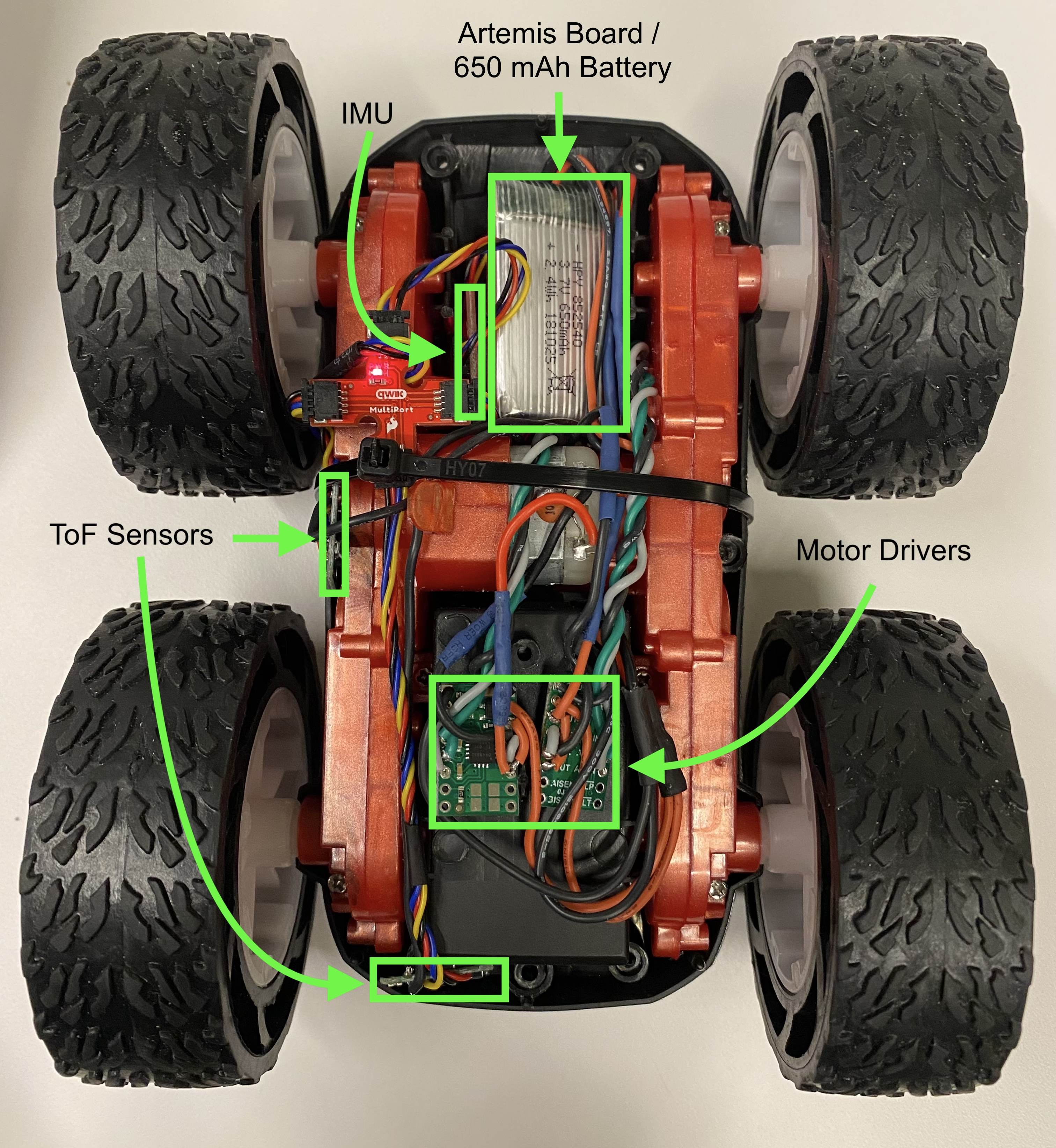
After everything was soldered together, the components were then secured into the car:

Here, the time-of-flight sensors were place at the front of the car and to the right, which was somewhat different from the initial plan to include them both at the front. The main reason for the difference is that it would be difficult to run the sensor wires around the motor drivers without incurring a significant amount of noise from EMI.
The motor drivers were then placed near the front, but more to the left side so that the wires would not run too close to the sensors. AS with the other components, wires were twisted to ensure minimal effects from EMI.
The rest of the components, including the IMU, Artemis board, and 650 mAh battery were then housed in the back of the car, which fit tightly enough to secure the IMU so that disturbances from vibrations or noise from the motor drivers would not be an issue.
Calibration:
Next, to ensure that the car was capable of moving along the ground, the following program was used to command the robot to drive forward for 3 seconds:
while(millis() - prev < 3000) {
  analogWrite(A15,0);
  analogWrite(A16,pwm);
  analogWrite(4,0);
  analogWrite(A5,pwm);
}
analogWrite(A15,255);
analogWrite(A16,255);
analogWrite(4,255);
analogWrite(A5,255);
After testing a few PWM values, it was found that the minimum PWM value required for the robot to still move on the ground was about 30.
However, during these measurements, it was observed that the robot would not move in a perfectly straight line and would deviate somewhat to the left. To address this error, a calibrating factor \(\alpha\) was added to the program, which controlled the percent increase from the PWM value in the left motor and the percent decrease in the PWM value in the right motor from their respective nominal values:
analogWrite(A15,0);
analogWrite(A16,round(pwm*(1.0+alpha)));
analogWrite(4,0);
analogWrite(A5,round(pwm*(1.0-alpha)));
After a bit of tweaking, a conversion factor of \(\alpha = 0.1\) was found to correct the robot’s path into a straight line, which can be seen in the following video, where the robot remains partially over the red line for up to 6 tiles (6 feet):
Open Loop Control:
Finally, to demonstrate the open-loop control capabilities of the robot, a simple program that used commands to go forward and spin for various amounts of time was implemented:
// forward
analogWrite(A15, 0);
analogWrite(A16,round(pwm_v*(1.0+alpha)));
analogWrite(4,0);
analogWrite(A5,round(pwm_v*(1.0-alpha)));
delay(750);
// turn CCW
analogWrite(A15,round(pwm_w*(1.0+alpha)));
analogWrite(A16,0);
analogWrite(4,0);
analogWrite(A5,round(pwm_w*(1.0-alpha)));
delay(500);
// forward
analogWrite(A15,0);
analogWrite(A16,round(pwm_v*(1.0+alpha)));
analogWrite(4,0);
analogWrite(A5,round(pwm_v*(1.0-alpha)));
delay(1000);
// turn CCW
analogWrite(A15,round(pwm_w*(1.0+alpha)));
analogWrite(A16,0);
analogWrite(4,round(pwm_w*(1.0-alpha)));
analogWrite(A5,0);
delay(500);
The effect of this was to basically go forward and do a fast U-turn in the middle: