Lab 3: Time of Flight Sensors
This lab was primarily focused on setting up the Time of Flight (ToF) (VL53L1X) sensors used to make depth measurements. The goal is ultimately give sensory feedback about the robot’s surrounding environment, which will play a crucial role in localization and mapping.
Setup:
To start off, a quick look at the sensor datasheet tells us that the sensor I2C address is set to 0x52 for all sensors.
Since the robot must communicate to both time of flight sensors individually, a workaround is required that either involves using the shutdown pins (labeled XSHUT) constantly to turn only one sensor one at a time before collecting the data, or using shutdown pins at the start and changing the address of one of the ToF sensors.
Because the sensors must operate ideally with as little latency as possible to get effective sensory feedback from its environement, the second approach is more favorable since it avoids the additional latency per measurement of shutting down each sensor in exchange for a small overhead latency cost of setting up the new I2C address.
Wiring:
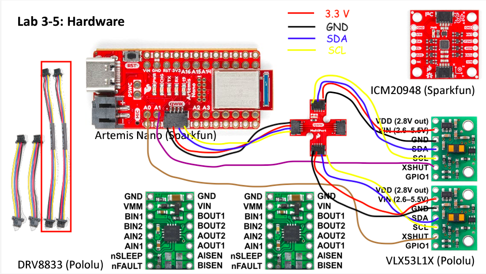
To pull this strategy off, the following wiring diagram was used:
After cutting and soldering the necessary wires, the final product of both sensors connected to the Artemis board can be seen below:
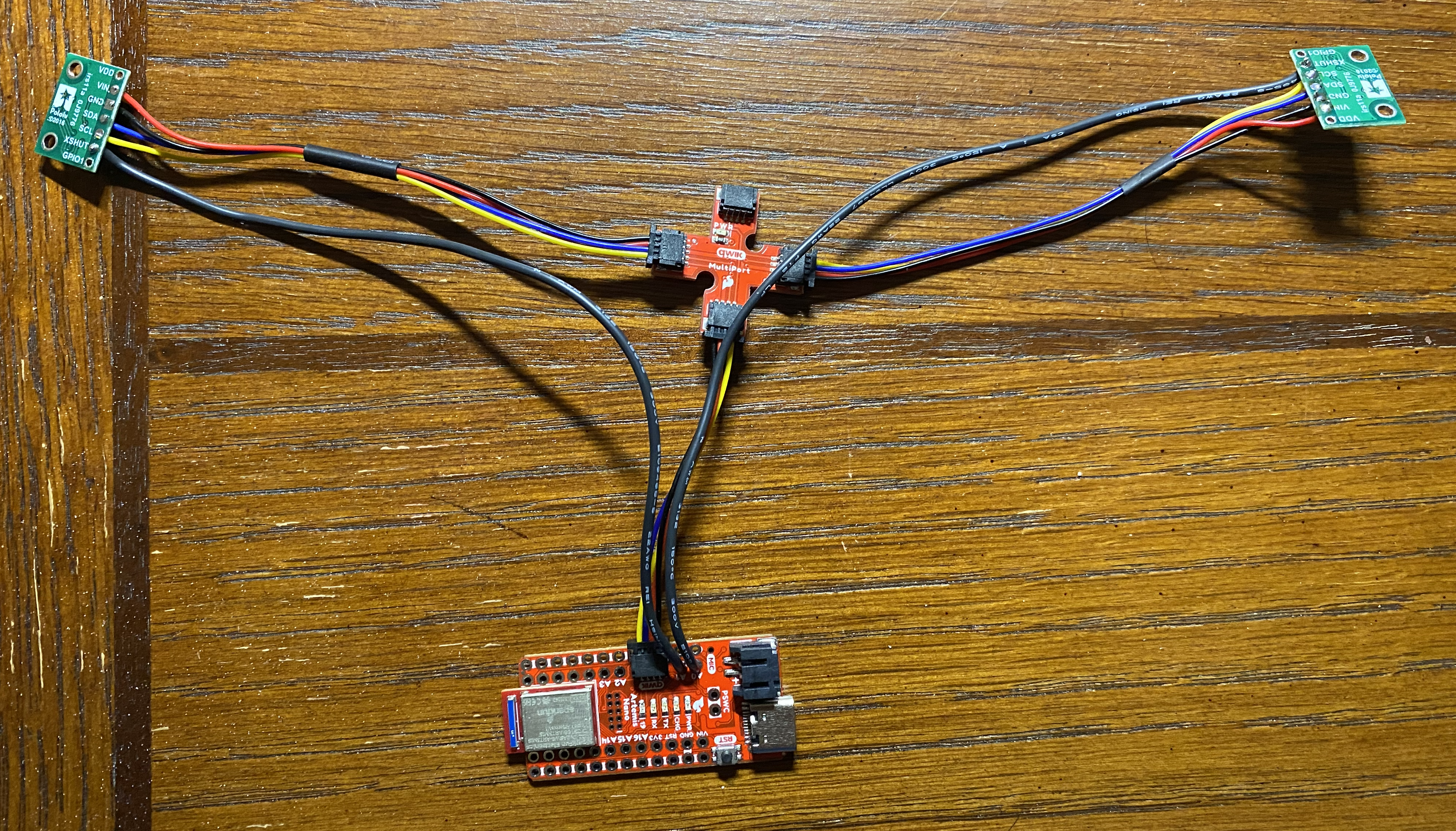
As mentioned before, the use of the shutdown pins is necessary to allow the Artemis board to communicate to both sensors, and hence these are connected to pins 0 and 1. Furthermore, notice that we use the longer, 100 mm QUIIC cables to allow for greater flexibility in the range of placements for the sensors on the robot.
In particular, a favorable place to put the sensors would ideally be in the front of the robot and possibly around the sides or back in order to get a better coverage of the surrounding environment. This way, the robot would not need to rotate around as much in order to fully map out its nearby surroundings.
However, since the field of view of the sensors only amounts to at most 27 degrees per sensor, it will inevitably fall short of the full 360 degree range, and hence compromise must be made. If the sensors are placed at the front and back alone, the blind spots at the sides would pose the risk of missing walls parallel to the direction of travel.
Placing sensors along the sides would somewhat mitigate this, but then the robot would need to turn all the way around to get information about the obstacles behind it.
A different approach would also be to placing both sensors in the front, which would somewhat reduce noise and possibly improve the effective range of the sensors to longer distances, although this improvement is less important since the sensors are already good up to depths of at least a couple of meters.
Hence, a middle ground of placing the sensors at the front corners would probably be best, as the robot would be able to avoid crashing into objects directly in front and to the sides.
Sensor I2C Address:
To verify that the Artemis board can successfully communicate with the ToF sensors, we use the example Wire_I2C script from the Apollo3 board library, which reads out the I2C address after connecting:

From here we see that the Serial Monitor displays the address 0x29 instead of the default address 0x52. However, in binary these correspond to 00101001 and 01010010, respectively, which are just the same strings, except the Serial Monitor output is bitshifted to the right with an additional leading 0.
This makes sense since the I2C protocol adds an additional leading bit to indicate reads/writes in front of the 7-bit address of the ToF sensor.
Characterizing the Sensor:
According to the datasheet, the ToF sensors have three modes: short, medium, and long. Each mode offers a different tradeoff between the effective range of the sensor and the robustness of the sensor under ambient lighting conditions. The name of each mode corresponds to the effective range it offers, which starts at 1.36 meters for the short mode and goes up to 3.6 meters for the long mode.
Since the robot must ideally operate well in any lighting condition, I opted to instead use the short mode, although the rated effective distance might pose performance limitations when implementing localizing and mapping algorithms.
Under the short mode, I then tested the sensor at various measured distances from a box and a caliper to record the ground truth, which is shown below:
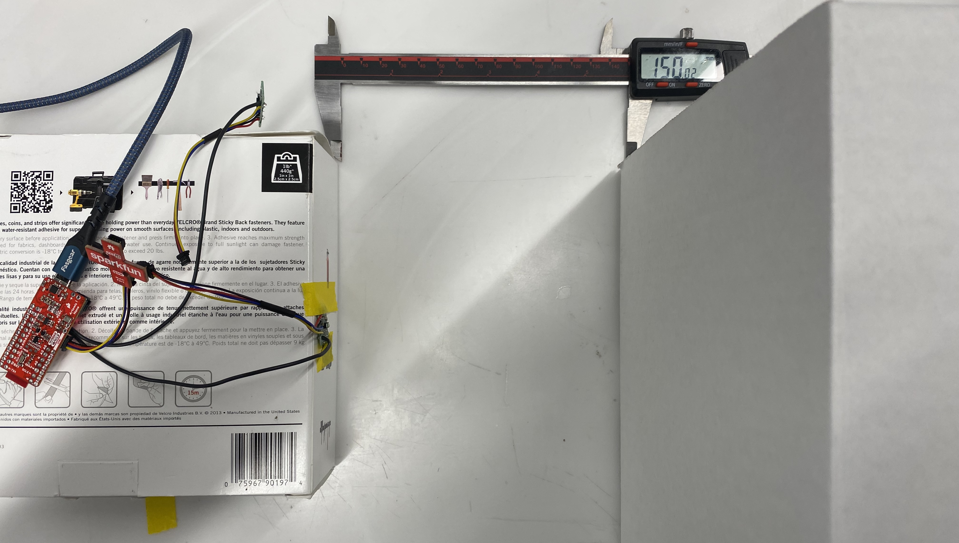
Note that the setup uses a white box in very bright lighting, which might not be representative of the sensor’s best or average performance. However, it does serve as a good lower bound on the best it can do.
After averaging groups of 30 measurements sampled 50 mm apart, I obtained the following results:
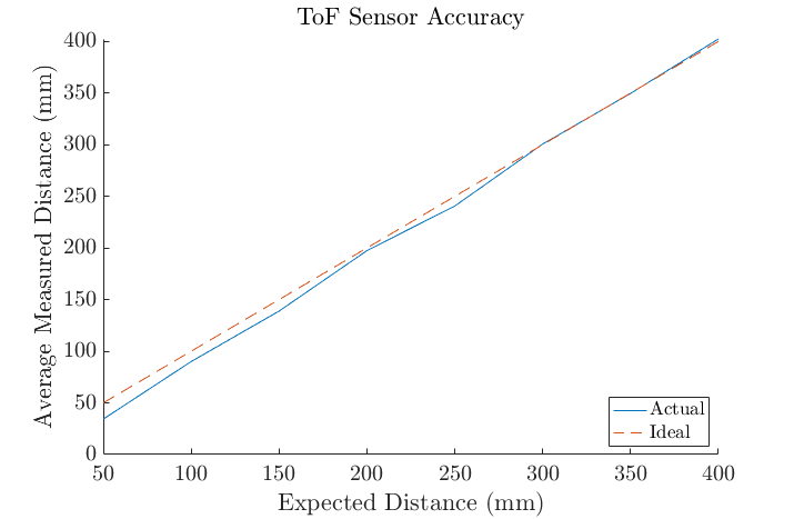
From here we observe that measurements follow the ground truth quite accurately, with an average difference of no more than 10 mm. We also observe that the accuracy degrades a bit if the sensor is too close to the box.
To see how repeatable the sensor measurements are, I also visualized the standard deviation of at each distance:
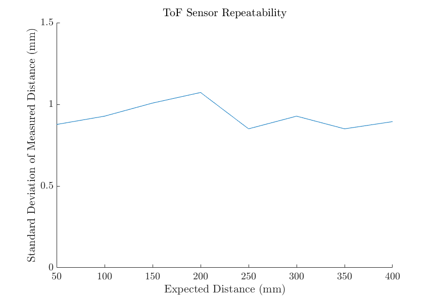
From here we see that the variability in the sensor output is about 1 millimeter or less from the mean on average, and hence measurements should generally be expected to lie somewhere in a range of 1 millimeter above and below the measured value.
Next, to produce an estimate about the lower endpoint of the ToF sensor’s range, I reduced the distance from the box until the sensor readings went to 0, which came out to around 25 millimeters.
To get an estimate of the higher endpoint, I moved the sensor away from a wall until the readings began to decrease with distance and stopped making sense. This came out to around 2.3 meters, which is quite a bit more than the reported range of 1.36 meters in the data sheet. However, the method I used can only really provide an upper bound on the high end of the dynamic range, as it does not test whether the depth measurements are still linear with distance up to 2.3 meters.
Finally, to measure the ranging time of the sensor, I tested the latency between executing the startRanging() function and receiving the sensor data.
Since there might be cases where the sensor collects data multiple times before calling stopRanging(), a comparison between the averaged latencies including calls of clearInterrupt() and stopRanging() over 30 measurements is shown in the table below:
| Including clearInterrupt() and stopRanging() | Ranging Time (ms) |
|---|---|
| Yes | 51.55 |
| No | 50.60 |
From here we see that the added latency required to stop the measurements is minimal at best and is generally around 50 milliseconds. Admittedly, this also includes the latency to print to the Serial monitor, and therefore might not be very accurate. A better way might be to rapidly store values into arrays and then to send these over Bluetooth.
Using Two ToF Sensors:
As previously discussed, the addition of the second ToF sensor requires using the shutdown pins of each sensor and then rewriting the I2C address of one of the sensors. This required the following code to set up the pins:
#define SHUTDOWN_PIN_1 0
#define SHUTDOWN_PIN_2 1

#define NEW_ADDRESS 10

SFEVL53L1X distanceSensor1(Wire, SHUTDOWN_PIN_1);
SFEVL53L1X distanceSensor2(Wire, SHUTDOWN_PIN_2);
I then set the pin values to rewrite the I2C address using the following in the setup() function:
// Make distance sensor addresses different at startup
pinMode(SHUTDOWN_PIN_1, OUTPUT);
pinMode(SHUTDOWN_PIN_2, OUTPUT);

digitalWrite(SHUTDOWN_PIN_1,LOW);
digitalWrite(SHUTDOWN_PIN_2,HIGH);

distanceSensor2.setI2CAddress(NEW_ADDRESS);

digitalWrite(SHUTDOWN_PIN_1,HIGH);
digitalWrite(SHUTDOWN_PIN_2,HIGH);

distanceSensor1.setDistanceModeShort();
distanceSensor2.setDistanceModeShort();
The main loop then set up the sensor measurements from each sensor, one at a time, and printed to the Serial Monitor:
distanceSensor1.startRanging(); //Write configuration bytes to initiate measurement
while (!distanceSensor1.checkForDataReady())
{
  delay(1);
}
int distance1 = distanceSensor1.getDistance(); //Get the result of the measurement from the sensor
distanceSensor1.clearInterrupt();
distanceSensor1.stopRanging();

distanceSensor2.startRanging(); //Write configuration bytes to initiate measurement
while (!distanceSensor2.checkForDataReady())
{
  delay(1);
}
int distance2 = distanceSensor2.getDistance(); //Get the result of the measurement from the sensor
distanceSensor2.clearInterrupt();
distanceSensor2.stopRanging();
This allowed me to successfully read out both sensors:
Sensor Speed:
The code I used so far to read from two ToF sensors essentially just waits for the sensor measurement to be sent over, and pauses all other tasks during this waiting period. Considering that the robot will need to run many tasks in the background besides simply reading sensor measurements, this is pretty inefficient.
A more efficient loop can be found in the following code:
distanceSensor1.startRanging(); // Write configuration bytes to initiate measurement
distanceSensor2.startRanging();

while (!distanceSensor1.checkForDataReady() || !distanceSensor2.checkForDataReady())
{
     Serial.print("T:");
     Serial.println(millis());
}

int distance1 = distanceSensor1.getDistance(); //Get the result of the measurement from the sensor
distanceSensor1.clearInterrupt();
distanceSensor1.stopRanging();

int distance2 = distanceSensor2.getDistance(); //Get the result of the measurement from the sensor
distanceSensor2.clearInterrupt();
distanceSensor2.stopRanging();
Here, the main loop prints time stamps to the Serial Monitor instead of simply inserting delays. By moving the relevant tasks inside the loop, the loop can execute whatever tasks it needs while waiting for the sensor data to arrive.
We then get the following output:
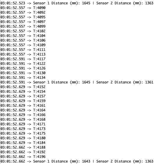
From here we find that the main loop repeats once everyy 40 - 50 milliseconds. This latency mainly is limited by the latency of the ranging time of each sensor, which is around 50 milliseconds by itself. there is also an unavoidable overhead of function cllas to startRanging(), clearInterrupt(), and stopRanging(), but given that the loop cannot really do better than the time it takes for each sensor measurement, the main loop is pretty much as optimized as it can be.
The latency of the inner while loop seems to range from 2 - 5 milliseconds, which is essentially limited by the latency of the Serial.print() commands, as there is very little inside the loop.
Bluetooth:
Finally, I made additional changes to the Bluetooth code base from Lab 2 to record ToF sensor measurements over a 5 second period. On the side of the Artemis board, this involved the addition of the following code:
case GET_TOF_5s_RAPID:
    int tof_prev;
    int tof_count;
    bool tof_measurement;

    // Write string back
    tx_estring_value.clear();
    tof_prev = millis();
    tof_count = 0;
    tof_measurement = false;

    distanceSensor1.startRanging(); // Write configuration bytes to initiate measurement
    distanceSensor2.startRanging(); // Write configuration bytes to initiate measurement

    while(millis() - tof_prev < 5000){
      if (distanceSensor1.checkForDataReady() && distanceSensor2.checkForDataReady())
      {
         tx_estring_value.append("T:");
         tx_estring_value.append(int(millis()));
         int distance1 = distanceSensor1.getDistance(); //Get the result of the measurement from the sensor
         int distance2 = distanceSensor2.getDistance(); //Get the result of the measurement from the sensor

         tx_estring_value.append("|D1:");
         tx_estring_value.append(distance1);
         tx_estring_value.append("|D2:");
         tx_estring_value.append(distance2);
         tof_count++;
         tof_measurement = true;
      }

      if (tof_count >= 4 || tx_estring_value.get_length() >= MAX_MSG_SIZE - 50 ) {
        tof_count = 0;
        tx_characteristic_string.writeValue(tx_estring_value.c_str());
        tx_estring_value.clear();
      }
      else if (tof_measurement){
        tx_estring_value.append("|");
        tof_measurement = false;
      }
    }
    tx_estring_value.clear();
    distanceSensor1.clearInterrupt();
    distanceSensor1.stopRanging();
    distanceSensor2.clearInterrupt();
    distanceSensor2.stopRanging();

    break;
I then added the following notification handler to the Python code:
async def get_tof_5s_rapid(uuid,byte_array):
    global time_millis
    global depth1_mm
    global depth2_mm
    global temp5s_str

    temp5s_str = ble.bytearray_to_string(byte_array)
    temp5s_list = temp5s_str.split("|")
    for i in range(0,len(temp5s_list),3):
        time = temp5s_list[i]
        depth1 = temp5s_list[i+1]
        depth2 = temp5s_list[i+2]
        time_millis.append(time[2::])
        depth1_mm.append(depth1[3::])
        depth2_mm.append(depth2[3::])
This sent roughly 600 data points from each sensor, which were then plotted using Matplotlib:
plt.figure(figsize=(8, 6), dpi=80)

# Plot data
line1, = plt.plot(time_millis,depth1_mm)
line2, = plt.plot(time_millis,depth2_mm)

# Label plot
plt.legend(handles = [line1,line2],labels = ['ToF Sensor 1','ToF Sensor 2'])
plt.xlabel('Time (ms)')
plt.ylabel('Distance (mm)')
plt.title('ToF Sensor Data Over 5 Seconds')
plt.savefig('ToFData.png')
This ultimately resulted in the following graph:
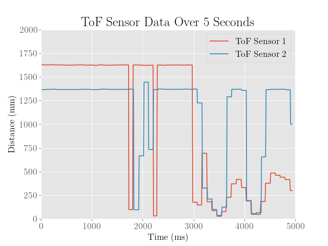
From here we see that the data fluctuates quite a bit, which is mainly from waving my hand over the sensors to test how responsive they are. Although the graph looks as if the derivative isn’t quite continuous at certain points, the result seems overall quite successful.